• Our booking engine at tickets.railforums.co.uk (powered by TrainSplit) helps support the running of the forum with every ticket purchase! Find out more and ask any questions/give us feedback in this thread!

Point motors (OO) - another query (bump)?

Status
Not open for further replies.

30907

Veteran Member
Joined
30 Sep 2012
Messages
17,989
Location
Airedale
Hi all.

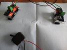
I have finally got around to installing the first two point motors at Charmouth and have hit problems:
when installed under the points, they don't consistently throw. The points themselves are in good order, if on the elderly side.
(Even disconnected from the points, one of them seems only to work in one direction, so possibly faulty?.

1. Would a CDU (Capacitor Discharge Unit not Frau Merkel's Party!) possibly resolve the problem?
2. With a CDU, am I asking too much to throw two points (a crossover) simultaneously?
3. Any other thoughts/experience?

(Gaugemaster, with Peco points and Peco passing-contact switch, 16v ac feed, though I suspect those make no difference.)

Mamy thanks in advance.
 
Sponsor Post - registered members do not see these adverts; click here to register, or click here to log in
R

RailUK Forums

TheEdge

Established Member
Joined
29 Nov 2012
Messages
4,489
Location
Norwich
A CDU will help give the oomph to make the solenoid throw fully and positively. But it won't do a great deal if the issue is that your points and motors are not aligned properly. Two points at once shouldn't be an issue for a decent CDU.
 

Cowley

Forum Staff
Staff Member
Global Moderator
Joined
15 Apr 2016
Messages
15,762
Location
Devon
A CDU will help give the oomph to make the solenoid throw fully and positively. But it won't do a great deal if the issue is that your points and motors are not aligned properly. Two points at once shouldn't be an issue for a decent CDU.

Yes to all of what @TheEdge says.

On my friend Paul’s railway each loop in the fiddle yard has two point motors that throw both points simultaneously via single switches using a CDU. It definitely shouldn’t be a problem @30907.
 

30907

Veteran Member
Joined
30 Sep 2012
Messages
17,989
Location
Airedale
Thanks both. Trip to Frizinghall Models and Railways (now in Baildon to confuse strangers) called for...
 

Bertone

Member
Joined
5 Nov 2021
Messages
184
Location
Hertfordshire
Are I correct in assuming that your point motors are the Gaugemaster surface mounted ones rather than the under the baseboard version?
 

30907

Veteran Member
Joined
30 Sep 2012
Messages
17,989
Location
Airedale
Are I correct in assuming that your point motors are the Gaugemaster surface mounted ones rather than the under the baseboard version?
Sorry, missed yours.
No, the ones I have tried are the Peco lookalike that clip under the point or use an extension piece (incredibly fiddly!) to go under the baseboard.
 

Bertone

Member
Joined
5 Nov 2021
Messages
184
Location
Hertfordshire
Sorry, missed yours.
No, the ones I have tried are the Peco lookalike that clip under the point or use an extension piece (incredibly fiddly!) to go under the baseboard.
I’ve used the Gaugemaster type PM-1 “motors” (with integrated switch contacts) which is fixed directly to the baseboard upderside with a good success rate of operation.
Regarding CDU’s, the one I use, switches six point ends at once on my layout. It is designated as “high power” but can’t remember now the make.
Is it possible you could post a photo of your setup?
 

30907

Veteran Member
Joined
30 Sep 2012
Messages
17,989
Location
Airedale
I’ve used the Gaugemaster type PM-1 “motors” (with integrated switch contacts) which is fixed directly to the baseboard upderside with a good success rate of operation.
Regarding CDU’s, the one I use, switches six point ends at once on my layout. It is designated as “high power” but can’t remember now the make.
Thanks
Is it possible you could post a photo of your setup?

OK a little more testing has happened with the motors detached from their points and with the switch. See picture. All wiring is correct per instructions, green being the return.
A CDU is in circuit, again correct.

The switch itself is fine (I have bypassed it to check) and there are no obvious bad connections.
But: a momentary current via the black wire (LH of switch) activates the rear solenoid, the same via the red wire (RH) produces only a slight buzz and no movement, whatever position the moving bit is in (forgotten my O-level Physics, it has a name).

To me it is almost as if the front solenoids are receiving only a tiny current, or are defective in some way - but it is odd to have the same fault on both.

Any ideas? TIA.

PS I've got a couple of PM-2s to try but they need soldering which I am not brilliant at...
 

Attachments

  • IMG_20220427_150517654.jpg
    IMG_20220427_150517654.jpg
    3.1 MB · Views: 21
Last edited:

Cowley

Forum Staff
Staff Member
Global Moderator
Joined
15 Apr 2016
Messages
15,762
Location
Devon
Thanks


OK a little more testing has happened with the motors detached from their points and with the switch. See picture. All wiring is correct per instructions, green being the return.
A CDU is in circuit, again correct.

The switch itself is fine (I have bypassed it to check) and there are no obvious bad connections.
But: a momentary current via the black wire (LH of switch) activates the rear solenoid, the same via the red wire (RH) produces only a slight buzz and no movement, whatever position the moving bit is in (forgotten my O-level Physics, it has a name).

To me it is almost as if the front solenoids are receiving only a tiny current, or are defective in some way - but it is odd to have the same fault on both.

Any ideas? TIA.

PS I've got a couple of PM-2s to try but they need soldering which I am not brilliant at...

Hmm. I’m not sure about this. I wonder if someone who’s good with electronics like @malc-c might have some thoughts?
 

Ediswan

Established Member
Joined
15 Nov 2012
Messages
2,851
Location
Stevenage
Any ideas? TIA.
Are you sure you have wiring correct ? The closest match I could find is this https://www.gaugemasterretail.com/magento/seep-gmc-pm10.html (fourth image). That shows the common connection in the middle. You image appears to show your common (green) wire at one end. That would result in the black wire energising one coil (correctly), but the red wire energising both coils, in series, which would be weak, and possiby pulling against each other.
 
Last edited:

Bertone

Member
Joined
5 Nov 2021
Messages
184
Location
Hertfordshire
Are you sure you have wiring correct ? The closest match I could find is this https://www.gaugemasterretail.com/magento/seep-gmc-pm10.html (fourth image). That shows the common connection in the middle. You image appears to show your common (green) wire at one end. That would result in the black wire energising one coil (correctly), but the red wire energising both coils, in series, which would be weak, and possiby pulling against each other.
I’ve just looked at the instructions as suggested by Ediswan above and similarly note that the common connection is in the centre of the terminal block. Worth trying a swop of wires or is your photo angle showing the block and wiring deceiving ?
 
Last edited:

30907

Veteran Member
Joined
30 Sep 2012
Messages
17,989
Location
Airedale
I’ve just looked at the instructions as suggested by Ediswan above and similarly note that the common connection is in the centre of the terminal block. Worth trying a swop of wires or is your photo angle showing the block and wiring deceiving ?

Are you sure you have wiring correct ? The closest match I could find is this https://www.gaugemasterretail.com/magento/seep-gmc-pm10.html (fourth image). That shows the common connection in the middle. You image appears to show your common (green) wire at one end. That would result in the black wire energising one coil (correctly), but the red wire energising both coils, in series, which would be weak, and possiby pulling against each other.
Thank you both.

The instructions on the back of mine have A B C in order with C as Common!
I must say I found that odd, so I will try your suggestion, and your explanation makes sense.
 

Ediswan

Established Member
Joined
15 Nov 2012
Messages
2,851
Location
Stevenage
Do you have a mulimeter with a resistance range ? If so, measure between the three combinations of two terminals. Two combinations should be roughly the same. The other combination should be the sum of the first two. The combination with the higher resistance between them is the A and B terminals.
 

30907

Veteran Member
Joined
30 Sep 2012
Messages
17,989
Location
Airedale
Success! Many thanks to you sleuths.
A mail to Gaugemaster will follow (cc FMR as they have some of that batch stock).
 

Ediswan

Established Member
Joined
15 Nov 2012
Messages
2,851
Location
Stevenage
Gaugemaster have replied- they claim to have notified all retailers when the error was discovered... and corrected the 5k+ they still had in stock.
Any chance you could post an image of the offending instructions ? It seems an odd mistake to make with something that has been the same for many years.
 

malc-c

Member
Joined
1 Dec 2017
Messages
990
Sorry I'm late to the party and the problem has since been identified and correction has resulted in the issue being resolved.
 

30907

Veteran Member
Joined
30 Sep 2012
Messages
17,989
Location
Airedale
Any chance you could post an image of the offending instructions ? It seems an odd mistake to make with something that has been the same for many years.
As requested. Doesn't want to go portrait, sorry.
 

Attachments

  • 20220428_121648~2.jpg
    20220428_121648~2.jpg
    796.2 KB · Views: 14

malc-c

Member
Joined
1 Dec 2017
Messages
990
LOL - that'll work.... NOT !! :D

Untitled.png

Been a while since I wired up solenoid motors, but one way to wire two up for a crossing is shown below. Or you could just wire A to A, and B to B and rotate one of the motors so that they move in opposite directions when the passing contact switch is moved. Firing two or more motors at the same time does need a CDU in my opinion.
Untitled1.png
 
Last edited:

Ediswan

Established Member
Joined
15 Nov 2012
Messages
2,851
Location
Stevenage
As requested. Doesn't want to go portrait, sorry.
Thanks.

The only changes appear to be the diagram, and the position of 'FOR LOW VOLTAGE INDOOR USE ONLY'.

The text says the terminals 'are labelled A, B (coils) and C (common)' and later to 'Terminal C'. In the previous version, the diagram showed 'COM' rather than 'C'. Maybe somebody decided that the diagram should exactly match the text, then the error crept in.
 

30907

Veteran Member
Joined
30 Sep 2012
Messages
17,989
Location
Airedale
Please allow me to bump this thread (thanks for the advice again).

This time it's the basic Gaugemaster PM2 motors (my soldering is now tolerable!).

I'm struggling to get them to throw properly (under the points through a generous slot in the baseboard). 3 of 4 that I've done work either one way only or not at all.

They work fine under non-load conditions. As far as I can see from underneath, the moving bit of the motor (armature?) moves partway across but then snaps back.

Does anyone use these, and have any advice on what I am doing wrong.
 

malc-c

Member
Joined
1 Dec 2017
Messages
990
Are you using a capacitor discharge unit to drive them as recommended in the instruction leaflet ?
 

malc-c

Member
Joined
1 Dec 2017
Messages
990
In that case I would have thought there was enough power in the motor to overcome the spring in the point motor. Is this just one motor or are all of them having the same issue ?

Are you firing one motor or two in parallel for the cross-over. If the latter then it may be that the CDU isn't capable of switching multiple solenoids
 
Last edited:

30907

Veteran Member
Joined
30 Sep 2012
Messages
17,989
Location
Airedale
Oops! When I said yes, I was wrong. The CDU is set up right, and can fire a crossover.
But I am using a roving lead to test the motors under the baseboard, not having an apprentice to move switches :) - and I had wired it to the input side of the unit, so it was bypassing it :)

Thanks for making me check. Initial results are positive, so now I need to complete the installation.

Apologies again.
 
Status
Not open for further replies.

Top