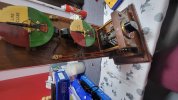
I've just picked up my first LNER combined block instrument for an up / down line but i'm failing at the first hurdle in trying to wire this thing up. After testing with a power supply, voltage across connectors 10 and 11 control the upper dial and reversing the polarity has the intended effect in switching between TOL and Line Clear. My struggle now is how to correctly wire up the bottom dial. I had assumed one of the rear connectors was a master 'power in' line, with the commutator deciding which other pegs to activate when turned to close the circuit but the combinations I'm finding are confusing me. If anyone has knowledge in this type of instrument and a simple wiring diagram, it would be greatly appreciated.
-
Our booking engine at tickets.railforums.co.uk (powered by TrainSplit) helps support the running of the forum with every ticket purchase! Find out more and ask any questions/give us feedback in this thread!
You are using an out of date browser. It may not display this or other websites correctly.
You should upgrade or use an alternative browser.
You should upgrade or use an alternative browser.
Wiring LNER block instrument
- Thread starter reidacus
- Start date
- Status
- Not open for further replies.
Sponsor Post - registered members do not see these adverts; click here to register, or click here to log in
R
RailUK Forums
Ashley Hill
Established Member
Try Dick the Signals site. There is a page of numerous diagrams. Page 19 could be yours.
If you don’t get any answers on here try The Signal Box website.
If you don’t get any answers on here try The Signal Box website.
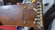
So the diagram you pointed out seems like the closest match but I don't have pins 1,2 and 3 but I don't think that's of any big consequence as the unit has no bell anyway. If I pass a positive voltage through pin 9, connect pins 7 and 8 together and connect pin 5 to the negative power supply, the commutator successfully switches the down line dial to TOL when selected. If I however connect a negative voltage to pin 6, when the commutator selects Line Clear, the down line still flicks to TOL. I've tried different permutations but it probably comes down to my lack of fully understanding the diagram. Any ideas where I'm going wrong?
Ashley Hill
Established Member
Perhaps the internal wiring needs modifying so the block reads over itself. That’s beyond my knowledge,someone here may know.So the diagram you pointed out seems like the closest match but I don't have pins 1,2 and 3 but I don't think that's of any big consequence as the unit has no bell anyway. If I pass a positive voltage through pin 9, connect pins 7 and 8 together and connect pin 5 to the negative power supply, the commutator successfully switches the down line dial to TOL when selected. If I however connect a negative voltage to pin 6, when the commutator selects Line Clear, the down line still flicks to TOL. I've tried different permutations but it probably comes down to my lack of fully understanding the diagram. Any ideas where I'm going wrong?
The upper dial works independently from the switch as it is powered from the adjacent box.
The lower dial is worked from the commutator switch, but is normally in series with the indicator dial in the adjacent box, so there needs to be a connection from the output terminal connected to the lower dial back to the 'Earth' terminal to complete the circuit. Just one or two 1.5v batteries will be enough to work the dials.
The lower dial is worked from the commutator switch, but is normally in series with the indicator dial in the adjacent box, so there needs to be a connection from the output terminal connected to the lower dial back to the 'Earth' terminal to complete the circuit. Just one or two 1.5v batteries will be enough to work the dials.
Thanks John. I'm using a variable power supply at the moment to give it the power it needs but my question really boils down to what terminal needs to be connected to what in order to achieve what you mention above as there's no indication what the output or earth terminals are. (I'm not doing anything with the top dial, only the bottom one).The upper dial works independently from the switch as it is powered from the adjacent box.
The lower dial is worked from the commutator switch, but is normally in series with the indicator dial in the adjacent box, so there needs to be a connection from the output terminal connected to the lower dial back to the 'Earth' terminal to complete the circuit. Just one or two 1.5v batteries will be enough to work the dials.
Sorry, we've a couple of these on display at St Albans South, but have not tried to wire them up yet. I've not yet had a chance to look at the diagram referred to in post #2 above, so can't offer any further advice at present.Thanks John. I'm using a variable power supply at the moment to give it the power it needs but my question really boils down to what terminal needs to be connected to what in order to achieve what you mention above as there's no indication what the output or earth terminals are. (I'm not doing anything with the top dial, only the bottom one).
Ploughman
Established Member
On the same subject.
How would I wire up a pair of block bells for display purposes only?
One side of a room to the other, not miles apart.
How would I wire up a pair of block bells for display purposes only?
One side of a room to the other, not miles apart.
The 'back contact' of the tapper should be permanently wired to one side of the bell. The other end of the bell goes to the negative of the battery or power supply (you will need around 6v). The front contact of the tapper should go to the positive of the battery. The centre-point of the two tappers are connected together (terminals possibly marked 'L' for 'Line'), as are the two negatives to the bells commoned up. Indeed you can use one battery supplying the +ve and -ve to both bells and the connection between the tappers means that a length of three-core cable can be used with the battery at one end or the other. (Apologies I don't have a decent drawing to hand!)On the same subject.
How would I wire up a pair of block bells for display purposes only?
One side of a room to the other, not miles apart.
Ploughman
Established Member
Thanks for that.
Just an update to close out this thread, I have success and its now working the way I expect it to. I posted over on the Signal Box and someone was able to guide me through each connection on the back of the instrument (https://signalbox.org/the-blower/topic/wiring-lner-block-instrument/#post-176618). Thanks to all who commented here and helped ")
- Status
- Not open for further replies.