-
Our new ticketing site is now live! Using either this or the original site (both powered by TrainSplit) helps support the running of the forum with every ticket purchase! Find out more and ask any questions/give us feedback in this thread!
You are using an out of date browser. It may not display this or other websites correctly.
You should upgrade or use an alternative browser.
You should upgrade or use an alternative browser.
A363 Bridge replacement Bradford-on-Avon
- Thread starter Snow1964
- Start date
- Status
- Not open for further replies.
Sponsor Post - registered members do not see these adverts; click here to register, or click here to log in
R
RailUK Forums
islandmonkey
Member
Me too. For work I probably visit BOA a couple of times a month and always pass the closed bridge and give it a curious glance.
Also, off-topic, but can I also pay my respects to anyone trying to cross from one side of the town to the other last week (and probably this week). Absolutely gridlocked by late morning on Thursday. Took 25-30 minutes to get off from Moulton Drive to get myself to Newtown. Unbelievable chaos
Also, off-topic, but can I also pay my respects to anyone trying to cross from one side of the town to the other last week (and probably this week). Absolutely gridlocked by late morning on Thursday. Took 25-30 minutes to get off from Moulton Drive to get myself to Newtown. Unbelievable chaos
WesternBiker
Member
I'm trying to envisage how those deck panels relate to the beams that have gone in? The beams have rows of tightly spaced upright bolts on the top, but I'm struggling to see how they relate.3 main beams, 2 went in this morning, presumably other one will be tonight
Seem to have opted more for a light grey colour rather than Cotswold stone colour to match the surroundings
View attachment 141234View attachment 141235View attachment 141236View attachment 141237View attachment 141238
Will probably automerge
Update Monday 21 August 2023
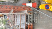
4 new photos, 2 showing 3rd main beam now in, 2 with large stack of deck panels
View attachment 141310View attachment 141311View attachment 141312View attachment 141313
Snow1964
Established Member
Network Rail were supposed to have finished in May, and on that basis a road closure of next bridge across Avon at Staverton was authorised for 5 month closure for Wessex Water works July-December. No one postponed that.Also, off-topic, but can I also pay my respects to anyone trying to cross from one side of the town to the other last week (and probably this week). Absolutely gridlocked by late morning on Thursday. Took 25-30 minutes to get off from Moulton Drive to get myself to Newtown. Unbelievable chaos
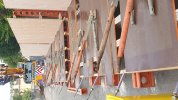
The deck panels are only about one traffic lane wide, took a photo from end of compound to show it, they also have skew ends as bridge is on a skew so span for each deck panel slightly longer.I'm trying to envisage how those deck panels relate to the beams that have gone in? The beams have rows of tightly spaced upright bolts on the top, but I'm struggling to see how they relate.
Also took couple of photos with zoom and will see there appears to have been some sort of black bedding strip added since yesterday for deck panels to side of bolts. The outer edges have some brackets which must be something to do with sides of bridge.
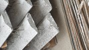
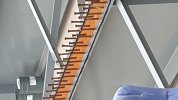
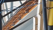
The "deck panels" are unlike anything I remember seeing before, but one thing I do know is that the posh term for the "bolts" on top of the beams is "shear connectors". Their role is to ensure that the beams "act compositely" with the concrete deck that will be poured around them. Without them, the concrete might slide over the beams when loads are applied.
WesternBiker
Member
Network Rail were supposed to have finished in May, and on that basis a road closure of next bridge across Avon at Staverton was authorised for 5 month closure for Wessex Water works July-December. No one postponed that.
The deck panels are only about one traffic lane wide, took a photo from end of compound to show it, they also have skew ends as bridge is on a skew so span for each deck panel slightly longer.
Also took couple of photos with zoom and will see there appears to have been some sort of black bedding strip added since yesterday for deck panels to side of bolts. The outer edges have some brackets which must be something to do with sides of bridge.
View attachment 141350View attachment 141351View attachment 141352View attachment 141353
The "deck panels" are unlike anything I remember seeing before, but one thing I do know is that the posh term for the "bolts" on top of the beams is "shear connectors". Their role is to ensure that the beams "act compositely" with the concrete deck that will be poured around them. Without them, the concrete might slide over the beams when loads are applied.
Thank you, both.
Presumably, more concrete is going to be poured over the decking beams, once in situ? I've looked at the diagrams provided to the Council showing the "new bridge", but it isn't clear from that how these decking beams fit into the design.
swt_passenger
Veteran Member
- Joined
- 7 Apr 2010
- Messages
- 32,785
Thank you, both.
Presumably, more concrete is going to be poured over the decking beams, once in situ? I've looked at the diagrams provided to the Council showing the "new bridge", but it isn't clear from that how these decking beams fit into the design.
The "deck panels" are unlike anything I remember seeing before, but one thing I do know is that the posh term for the "bolts" on top of the beams is "shear connectors". Their role is to ensure that the beams "act compositely" with the concrete deck that will be poured around them. Without them, the concrete might slide over the beams when loads are applied.
I think this is the product installation guide. Mentions a 55mm minimum overlap at the plank ends, then the whole thing is covered in rebar and a deck poured that locks it all together.
By the way, to find the product I did a Google search for “permanent formwork concrete planks” and had a look around for something that looked right…
Last edited:
Correct, those 'bolts' aka 'studs' are shear connectors.The "deck panels" are unlike anything I remember seeing before, but one thing I do know is that the posh term for the "bolts" on top of the beams is "shear connectors". Their role is to ensure that the beams "act compositely" with the concrete deck that will be poured around them. Without them, the concrete might slide over the beams when loads are applied.
The concrete panels are termed 'permanent formwork', laid (and resting on) the installed beams, rebar added, and then an in-situ concrete deck is cast on top; this creates a slab spanning between the main beams and also acts as an upper part of the steel beams as a compression flange by becoming an integral part of the deck construction by means of the shear connectors.
By using the concrete planks as permanent formwork, this removes the need to use falsework (aka scaffolding) to prop up temporary soffit formwork over a live railway.
Snow1964
Established Member
DelW
Established Member
- Joined
- 15 Jan 2015
- Messages
- 4,690
The threaded rods are Dywidag bars, widely used in temporary works including as formwork ties. I think that the horizontal resin faced plywood is the soffit formwork for a cantilever slab extending beyond the outer beam, and that the Dywidag bars are part of the support system for that. I believe you're right that the curved nuts will fit into the cup shaped anchorages on the top flanges of the beams. The exact construction sequence is puzzling me a bit at the moment though!
WesternBiker
Member
Thank you. V helpful!
I think this is the product installation guide. Mentions a 55mm minimum overlap at the plank ends, then the whole thing is covered in rebar and a deck poured that locks it all together.
By the way, to find the product I did a Google search for “permanent formwork concrete planks” and had a look around for something that looked right…
Snow1964
Established Member
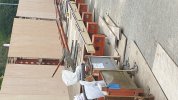
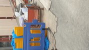
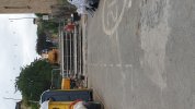
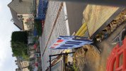
Most of the deck panels now in, also took so pictures in the compound with pallet full of some sort of spacers, powered wheelbarrows with tactile paving (but these might be for station, one platform is done, other isn't), and stored stone to rebuild the walls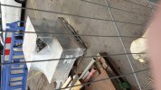
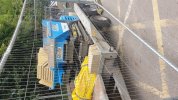
second photo is irrelevant to the bridge, but also at BoA this morning (excursion to Plymouth about to pick up),
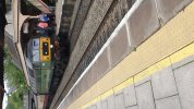


second photo is irrelevant to the bridge, but also at BoA this morning (excursion to Plymouth about to pick up),


Last edited:
DelW
Established Member
- Joined
- 15 Jan 2015
- Messages
- 4,690
Most of the deck panels now in, also took so pictures in the compound with pallet full of some sort of spacers, powered wheelbarrows with tactile paving (but these might be for station, one platform is done, other isn't), and stored stone to rebuild the walls
I think the items in the plastic shrink wrap are parapet anchorages, sets of four sockets linked with steel flats or bars. If so they'll be cast into the deck edge coping, and the parapet stanchion bolts will screw into them.
Parapets for road over rail bridges are taller than normal (1.8m IIRC) and designed for higher containment of vehicle impacts, so the anchorages are more substantial than in other bridges.
Snow1964
Established Member
Local update from Network Rail
This week has been lot of diverted overnight freight trains, via Berks and Hants and Bath Spa, which makes the decision to try and do the work overnight on the diversion route look pretty stupid, Network Rail has spun this clash into following text sent by email.
At the moment all the part assembled side panels are on the road blocking in the crane, so going to have to move them regardless if crane is leaving Friday morning
New photo Friday 25th August
Deck panels are in, crane has left, but none of the side formwork was lifted in.
This week has been lot of diverted overnight freight trains, via Berks and Hants and Bath Spa, which makes the decision to try and do the work overnight on the diversion route look pretty stupid, Network Rail has spun this clash into following text sent by email.
At the moment all the part assembled side panels are on the road blocking in the crane, so going to have to move them regardless if crane is leaving Friday morning
Bradford on Avon - St Margaret bridge Good morning,
We’re sorry that we haven’t been in touch about the crane work that took place last night.
We have been struggling to get a suitable window of opportunity to install concrete slabs and steel components within the limited time being provided to us between train movements on the track. As a consequence, the number of nights the crane has been working has had to be extended, to that which was previously communicated.
The crane will be in use this evening to continue with the installation of the bridge deck. Any components not installed will be dismantled and installed manually, during day time working as this removes the reliance on the closure of the railway.
The Crane will leave the site on Friday morning.
We are sorry for any disturbance this may have caused and we’ll be back in touch with a further update.
New photo Friday 25th August
Deck panels are in, crane has left, but none of the side formwork was lifted in.

Last edited:
Snow1964
Established Member
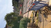
Some new photos 9th September
Since crane left 2 weeks ago, without lifting the falsework for the parapets, little seems to have happened apart from the unlifted parts seem to have been disassembled and are now being installed by hand in slow time. No sign of any rebar being installed for deck to be cast. However some timber panels are onsite presumably for the parapet walls.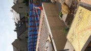
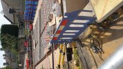
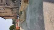
Update received by email from Network Rail 15th September
Since crane left 2 weeks ago, without lifting the falsework for the parapets, little seems to have happened apart from the unlifted parts seem to have been disassembled and are now being installed by hand in slow time. No sign of any rebar being installed for deck to be cast. However some timber panels are onsite presumably for the parapet walls.


Update received by email from Network Rail 15th September
Good evening,
We're sorry for the late message tonight but wanted to give you an update on the work we are carrying out on the bridge near you.
We'll be on site this weekend working between 8am and 6pm on both Saturday and Sunday. No work is scheduled for completion during the night time next week, so you should expect to see us working during the day.
Key dates for our programme and we'll be in touch nearer the time to advise of our the shift times.
- Deck construction in place by Tuesday 17 October
- Utility Services Reinstatement complete by Wednesday 22 November
- Removal of temporary services bridge by Tuesday 28 November
- Road Surfacing complete by Wednesday 29 November
- Road open - Thursday 30 November
These dates are subject to change. If this does happen, we will keep you updated.
Thank you for your patience and understanding as we continue to work here.
Last edited:
Snow1964
Established Member
WesternBiker
Member
Well, it's all progress, even if it does seem painfully slow.
Do you have any impression of what the locals think of the ongoing impact from all this?
I'm guessing traffic must be grim, though some may have found other ways around it. I suspect some of those a little further along St Margaret's street migh tbe happily getting used to the relative quiet...
Do you have any impression of what the locals think of the ongoing impact from all this?
I'm guessing traffic must be grim, though some may have found other ways around it. I suspect some of those a little further along St Margaret's street migh tbe happily getting used to the relative quiet...
Snow1964
Established Member
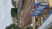
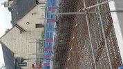
Some new photos 9th October, the deck and lower parapets have all been cast, and the falsework has just been removed from below the cast concrete.
All the removed temporary parts are now stacked, presumably awaiting collection.
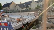
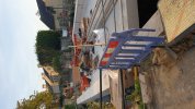
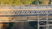
Looks like some metal parapets have been added during last 3 days
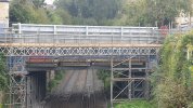
Some new photos, now looks like preparing to rebuild the side walls
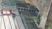
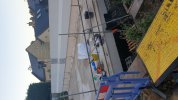
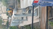
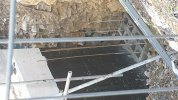
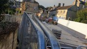
All the removed temporary parts are now stacked, presumably awaiting collection.


Looks like some metal parapets have been added during last 3 days

Some new photos, now looks like preparing to rebuild the side walls


Last edited:
Annetts key
Established Member
Lots of progress then 

WesternBiker
Member
That's quite a muscular design of parapet.
edwin_m
Veteran Member
Parapets of new road over rail bridges have to meet latest standards aiming to prevent a road vehicle breaking through and falling onto the track.That's quite a muscular design of parapet.
WesternBiker
Member
I thought that might be the case - though I've not seen one quite like this before. Understandable in this location - a relatively narrow bridge, busy main road, steep hill either side, plenty of lorries...Parapets of new road over rail bridges have to meet latest standards aiming to prevent a road vehicle breaking through and falling onto the track.
edwin_m
Veteran Member
There should be very few lorries, as there is a weight restriction a short distance away on the Town Bridge. But it is frequently ignored.I thought that might be the case - though I've not seen one quite like this before. Understandable in this location - a relatively narrow bridge, busy main road, steep hill either side, plenty of lorries...
edwin_m
Veteran Member
On some, but not all, of the most recent batch of photos, metal parapets have been added above the concrete ones, and I'd guess these meet the standard for electrification.Slightly disappointed but completely understandably the parapets appear not to be tall enough for electrification requirements (although raising them isn't too hard, and the bridge itself should be fine).
Snow1964
Established Member
Difficult to tell the exact height of parapet as road still needs to be laid, but based on herras fencing each end on existing footpath would say they will be about 1.7m (5.5 feet) above footpath surface height. Obviously will be error factor in my visual guessOn some, but not all, of the most recent batch of photos, metal parapets have been added above the concrete ones, and I'd guess these meet the standard for electrification.
What height is needed for electrification ?
Fairly sure 1.8m is the latest standard although it's all a bit academic as electrification would be quite far down the line (pun not intended) and the standards could change by then.Difficult to tell the exact height of parapet as road still needs to be laid, but based on herras fencing each end on existing footpath would say they will be about 1.7m (5'3") above footpath surface height. Obviously will be error factor in my visual guess
What height is needed for electrification ?
DelW
Established Member
- Joined
- 15 Jan 2015
- Messages
- 4,690
1.8m is my recollection but I think that one of the (fairly) recent changes was to add a substantial lateral design vehicle impact load at either 0.5m or 0.6m above the base. So I think a typical current design is 0.6m concrete upstand with a 1.2m steel or aluminium parapet above it.Fairly sure 1.8m is the latest standard although it's all a bit academic as electrification would be quite far down the line (pun not intended) and the standards could change by then.
I'd be very surprised if they didn't allow for OHLE even if it's a long time away. AIUI new footbridges on the SWR lines have to have OHLE clearance even though there's virtually zero chance of that replacing the existing third rail DC.
Allowing for OLE under the bridge is quite different from the parapets. I'd be very surprised if the under-deck clearance wasn't OLE-ready just from the location tbh as it's a flat deck.I'd be very surprised if they didn't allow for OHLE even if it's a long time away. AIUI new footbridges on the SWR lines have to have OHLE clearance even though there's virtually zero chance of that replacing the existing third rail DC.
Snow1964
Established Member
Plenty of clearance, there is a temporary crash deck (not yet removed) which is metal beams with wooden sheets above, the 3 main bridge beams are well clear of this. Must be about half metre between bottom of crash deck and lowest point of bridge beams, and of course space between top of trains and crash deck so probably at least 0.6m if not even moreAllowing for OLE under the bridge is quite different from the parapets. I'd be very surprised if the under-deck clearance wasn't OLE-ready just from the location tbh as it's a flat deck.
- Status
- Not open for further replies.

