• Our booking engine at tickets.railforums.co.uk (powered by TrainSplit) helps support the running of the forum with every ticket purchase! Find out more and ask any questions/give us feedback in this thread!

Auto Transformer Modelling using LT Spice.

kp_raileng

New Member
Joined
19 Feb 2024
Messages
3
Location
Nottingham
Hello,

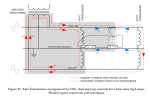
I am looking to model an ATF system using LT spice, however I am having trouble setting up a reliable system: I have modelled the centre tapped transformer as two 25 kV (peak) 50 Hz AC Voltage sources with a 180 degree phase shift; the Inductors (used to represent the Auto transformers) as 0.2 H; The train as a resistive load of 80 Ohm. The issue is when I check the current in the Voltage sources, I am getting 800 A peak. This is far greater than the current in the resistive load, which reads 300 A.

1. I would like to know whether anyone is able to give any advice as to whether I can make any improvements with my model to yield more realistic results.
2. I am also aware that Lt Spice is typically used for lower voltage electronics modelling. Is anyone able to recommend a similar free (and new user friendly) application that may be more suited to high voltage circuit modelling?
Please see the attached images for reference.

Circuit Diagram Voltage across resistive load (i.e. train) Current across resistive load
1708366771889.png1708366838406.png1708366927131.png


Many Thanks.
 
Sponsor Post - registered members do not see these adverts; click here to register, or click here to log in
R

RailUK Forums

Ediswan

Established Member
Joined
15 Nov 2012
Messages
2,858
Location
Stevenage
The current in each of the voltage sources will be the sum of the current in the inductors and resistor (where present) connected across it. Does I(V1) = I(L1)+I(L3)+I(R1) ?
I doubt the high voltage will upset that model LT Spice.
Should there be some coupling between the inductors, the lower half of the circuit doesn't appear to affect R1.
 

kp_raileng

New Member
Joined
19 Feb 2024
Messages
3
Location
Nottingham
Hello,

Thank you for getting back to me. I have checked out the link you provided, whereby a Spice directive was used to couple all inductors, I am struggling to understand how this realises Autotransformer functionality as all the Inductors are in series with each other. I have included a screenshot of the Auto Transformer arrangement from Garry Keenor's book "Overhead Line Electrification for Railways" (6th Edition), which I used for my LT Spice circuit. I would like to know whether anyone else is able to interpret / make a connection between these two diagrams and is willing to share their thoughts.
1708422309457.png
1708422014052-png.152776


Many Thanks.
 

Attachments

  • 1708422014052.png
    1708422014052.png
    70.3 KB · Views: 165

John Webb

Established Member
Joined
5 Jun 2010
Messages
3,072
Location
St Albans
Ought you to bear in mind that the train is not a pure resistive load? They carry one or more transformers to drop the voltage down to that needed by the motors.
 

kp_raileng

New Member
Joined
19 Feb 2024
Messages
3
Location
Nottingham
Ought you to bear in mind that the train is not a pure resistive load? They carry one or more transformers to drop the voltage down to that needed by the motors.
Hello, thanks for getting back to me. The idea was that I would initially check with a resistive load in order to check that current magnitudes are in accordance with the Image I provided from Garry Keenor's book in the previous post - the Resistance value chosen roughly corresponds to a 4 MW Active Power Load for the 25 kV Voltage, so I was trying to test whether the Current at the Voltage sources would be 1/4 the current of the Resistive Load.

However, the current waveform for the Voltage source is not what I am expecting (being sinusoidal between 0 and -1.6 kA), while the resistive load current is +/- 330 A. Please see the images below (Left: Current waveform at Voltage Source V1; Right: Current Waveform across resistive load R1).
1708431622525.png1708431696087.png
I'm essentially trying to figure out what I have done wrong with the circuit to end up with these currents, and based on other responses I think it may be to do with the inductors, however I am still not quite understanding the issue correctly and so was wondering whether anyone can see a potential solution of how to arrange / couple the inductors properly.

Many Thanks.
 
Last edited:

Ediswan

Established Member
Joined
15 Nov 2012
Messages
2,858
Location
Stevenage
Look at I(L1) and I(L3). Create a trace showing V(V1), I(R1), I(L1), I(L3).

Coupling inductors would require a K statement for each autotransformer. Also check the inductors have the correct phase relationship.
 

mike57

Established Member
Joined
13 Mar 2015
Messages
1,679
Location
East coast of Yorkshire
Haven't ever used the modelling software, back in the day everything was done with pen and paper so I may have missed something, and it is 40 years since i did this type of calc.

Looking at this simply each inductor will will have a reactance of about 62 ohms at 50Hz, which gives a reactive current of 800A if they are perfect inductors with no coupling between them, which your circuit would imply, which is what you get. I think the issue is the voltage source and inductors. Surely the Auto transformer would be modeled as a voltage source with some resistance (the winding resistance) and inductance in series.
 

buz33

Member
Joined
21 Nov 2009
Messages
16
Try adding something like:
Code:
K1 L1 L2 1.
K2 L3 L4 1.
The final parameter (mutual coupling coefficient) assumes perfect magnetic coupling between the transformer windings, in reality it will be less than 1.
 

Ediswan

Established Member
Joined
15 Nov 2012
Messages
2,858
Location
Stevenage
Haven't ever used the modelling software, back in the day everything was done with pen and paper so I may have missed something, and it is 40 years since i did this type of calc.

Looking at this simply each inductor will will have a reactance of about 62 ohms at 50Hz, which gives a reactive current of 800A if they are perfect inductors with no coupling between them, which your circuit would imply, which is what you get. I think the issue is the voltage source and inductors. Surely the Auto transformer would be modeled as a voltage source with some resistance (the winding resistance) and inductance in series.
I found a basic LT Soice autotransformer model I did a while back (240V to 120V). That works fine modelled as a pair of coupled inductors. The LT Spice inductor model includes series resistance, parallel resistance, parallel capacitance.

I have modelled the centre tapped transformer as two 25 kV (peak) 50 Hz AC Voltage sources with a 180 degree phase shift
This is a side question for anybody who understands the details of how ATF works.

The description here: https://en.wikipedia.org/wiki/25_kV_AC_railway_electrification#2_×_25_kV_autotransformer_system shows the split-phase supply being created by a local transformer. I am wondering whether the coupling between the phases within that transformer is required for the ATF system as a whole to work ? If so, that supply transformer would need to be modelled as well.
 
Last edited:

endecotp

Member
Joined
23 Apr 2014
Messages
221
I have checked out the link you provided, whereby a Spice directive was used to couple all inductors, I am struggling to understand how this realises Autotransformer functionality as all the Inductors are in series with each other.
View attachment 152777

Correct, in an autotransformer the inductances are in series. But that’s not the same as just putting two inductors in series; in an autotransformer the two coils share the magnetic field. Your model must express that.

(I find that schematic a bit confusing because the way they have put the four coils in a 2x2 layout. It would be clearer if they were all in-line. Note it is a 1:4 autotransformer.)


I have included a screenshot of the Auto Transformer arrangement from Garry Keenor's book "Overhead Line Electrification for Railways" (6th Edition), which I used for my LT Spice circuit. I would like to know whether anyone else is able to interpret / make a connection between these two diagrams and is willing to share their thoughts.
1708422014052-png.152776


Many Thanks.

I think your circuit may work if you couple L1 and L2, and L3 and L4 (as buz33 says).
 

boiledbeans2

Member
Joined
15 Oct 2020
Messages
515
Location
UK
I am struggling to understand how this realises Autotransformer functionality as all the Inductors are in series with each other.
I'm not sure I understand your question.

In reality, the autotransformer has only a single coil with intermediate taps on the secondary side. See this pic from Wiki

So the splitting of the coil (or inductor) is only to facilitate the modelling on the secondary side - to allow you to add a tapping. Therefore, they should always be in series.

Edit: Yeah follow the advice above about coupling. Your circuit right now is probably behaving like one with inductive and resistive loads only. No transformers present.
 
Last edited:

Pigeon

Member
Joined
8 Apr 2015
Messages
804
It is not a 4:1 autotransformer. It's two autotransformers, each 2:1 (or 1:1 with centre tap, which is another way of expressing the same thing).

The inductors for each autotransformer do need to be coupled, otherwise it isn't a transformer. But the two pairs for each transformer need to be separately coupled - coupling all four of them together is wrong, because it's two transformers, not one. This is PSPICE, not LTSPICE, so K cannot be 1, but 0.99 is good enough.

I've used only one autotransformer (with half the inductance), since they're both in parallel so will be doing exactly the same thing, and it is less confusing without the duplication.

It runs it for 10 seconds to allow the initial DC offset to decay (nearly) away; I plot only the last 0.1s.

It moans about having a voltage source & inductor loop if the inductors have no series resistance, so I have given it 0.05 ohms each, which is a pure guess, so it may well be wrong, but it doesn't matter.

It's easier to see what's going on if you increase the autotransformer inductance, say by 10x or more, since the reactive current is then much less and the phase shifts are much smaller. Doesn't affect the principle of course.

It works fine as long as the supply voltage is NOT centre-tapped to earth. The vector sum of the currents in L1 and L2 equals the current in R1, and the current in R1 is twice the current in the voltage sources.

It DOESN'T work if the supply IS centre-tapped to earth. The current in R1 remains the same, since it still has 25kV (RMS) across it. The currents in the two inductors just do their own thing independently. V1 supplies the current in R1 + the current in L1, while V2 supplies the current in L2 only, and the currents in L1 and L2 are equal. And this is exactly what you'd expect to happen, because the supplies are perfect voltage sources feeding it through zero impedance connections, so no matter what loads you put on it, they still see exactly 25kV at phase angle 0, and so do the autotransformers; neither thing can "see" the other, so there is no interaction between them and you won't see any "autotransformer magic".

The conclusion is that the diagram you are basing it on is possibly wrong, and is certainly incomplete. The connections between the various parts of the system are long enough that not only is their resistance significant, but their inductance and their capacitance are also beginning to need taking account of. Also the supply transformer will not be an ideal voltage source, nor will its impedance be purely resistive. None of this is shown in that diagram, but it all makes a difference.

SPICE (any variant) is perfectly able to handle the magnitudes of voltage and current for a circuit like this, but it can't simulate factors it hasn't been told about. That's why modelling "extreme" systems like this can be tricky: you need to take into account lots of things that normally don't have enough effect for you to notice or think about, so you have to look carefully for all of these and then try and come up with reasonable values for them.

Code:
* ohle with autotransformer

.param ind=0.1
.param rpara=0.05

V1 1 10 SIN(0 35.36k 50)
V2 10 2 SIN(0 35.36k 50)

Rl1 1 3 {rpara}
L1 3 0 {ind}
L2 0 4 {ind}
Rl2 4 2 {rpara}
K1 L1 L2 0.99

R1 1 0 80

.tran 1u 10 0 1m
 

apk55

Member
Joined
7 Jul 2011
Messages
439
Location
Altrincham
You need to build into the model other factors such as resistance of running rails and overhead line. Steel running rails can have significant resistance and will affect return currents
Also there is inductance of the line which can be significant.
 

Top