• Our booking engine at tickets.railforums.co.uk (powered by TrainSplit) helps support the running of the forum with every ticket purchase! Find out more and ask any questions/give us feedback in this thread!

'Fixed point' v Moveable switch

Status
Not open for further replies.

Peter Fox

Member
Joined
1 Mar 2018
Messages
60
On the Railway Accidents Archive is a report
Accident Returns: Extract for the Accident at Mansion House on 30th July 1877
where a train derailed at a set of points.

These points are described as 'fixed' (but not in the never moving sense) and are recognised in the report
as an obsolete and unreliable type.

The only other construction of points/switches I can think of which isn't the familiar blades moving between outer running rails
is what I'd call 'stub points' where the whole two running rails are shifted sideways between two sets of stub ends.

Anybody know?
 
Sponsor Post - registered members do not see these adverts; click here to register, or click here to log in
R

RailUK Forums

John Webb

Established Member
Joined
5 Jun 2010
Messages
3,072
Location
St Albans
The same points were involved in another accident on the 12th September - the report follows on directly from the one above. It seems that the railway were already involved in changing the 'fixed point' for a switchable one, but hadn't completed the work by the 12th Sept.

Bob Essery's book "Railway Signalling and Track Plans" (Ian Allan, ISBN 0 7110 3215 6, 2007) goes into some detail on trackwork but makes no mention of 'fixed points'. He does suggest that those interested in the subtle variations of permanent way might consult "Railway Permanent Way" by Hepworth and Lee, published in 1922.

It's not a term I've come across before, I have to admit.
 

Railsigns

Established Member
Joined
15 Feb 2010
Messages
2,503
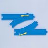
The description brings to mind an arrangement where an ordinary movable switch on one side of the points directs a train's wheels one way or the other depending on how it lies, while on the other side there's just a casting with a flangeway that splits two ways.

I think they're used on some tram lines.

It's the same principle that these toy railway points work on:

toy points.jpg
 
Last edited:

Peter Fox

Member
Joined
1 Mar 2018
Messages
60
Thanks for that very clear illustration Railsigns. Looking at it I can see why it's an inferior method unless all dimensions of rails and wheels are immaculate. I know it's a guess but I'd say a very good one.
 

DerekC

Established Member
Joined
26 Oct 2015
Messages
2,116
Location
Hampshire (nearly a Hog)
I think @Railsigns is right, as the summary on Railways Archive says:

Although Colonel Rich was uncertain about the causes of this accident, a similar event which occurred at the same place six weeks later, on 12 September 1877, caused him to revise his conclusion and decide that the "fixed", or single bladed, point was solely responsible.
And the text of the report on the second accident says:

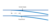
This junction is formed by a switch rail at the near sides, and a fixed point at the offside, the fixed point is 11 feet within the point of the switch................ These marks plainly indicate that the lending off side wheel of the engine took the wrong side of the fixed point, and that the near side wheels were pulled over the opposite rail at a point exactly opposite to the fixed point and 11 feet from the point of the switch
However I can't work out how this would reliably direct a train in both normal and reverse directions. I end up with something like the diagram below

1659619509646.png


Did they just hope the train would run straight, with the switch blade in the "normal" position? The toy train example works because the track is double flanged.
 
Last edited:

racyrich

Member
Joined
25 Jan 2014
Messages
207
Did they just hope the train would run straight, with the switch blade in the "normal" position? The toy train example works because the track is double flanged.

Relying on the switch blade to act as a check rail. No thanks.
 

Railsigns

Established Member
Joined
15 Feb 2010
Messages
2,503
However I can't work out how this would reliably direct a train in both normal and reverse directions.

Did they just hope the train would run straight, with the switch blade in the "normal" position?
Because a train's wheels are a set distance apart on their axles, a wheel running on the fixed point must go in the same direction as the one running on the switched point, according to which way the switch is set.
 

DerekC

Established Member
Joined
26 Oct 2015
Messages
2,116
Location
Hampshire (nearly a Hog)
Because a train's wheels are a set distance apart on their axles, a wheel running on the fixed point must go in the same direction as the one running on the switched point, according to which way the switch is set.
Well yes, but the switch blade can only work in both normal and reverse if it guides the back of the flange - and with the "fixed point" being well past the toe of the movable switch, that seems a bit hopeful! I guess it was hit and miss, that's why the idea was abandoned (except on tramways, it seems).
 

Railsigns

Established Member
Joined
15 Feb 2010
Messages
2,503
Well yes, but the switch blade can only work in both normal and reverse if it guides the back of the flange - and with the "fixed point" being well past the toe of the movable switch, that seems a bit hopeful! I guess it was hit and miss, that's why the idea was abandoned (except on tramways, it seems).
In theory a check rail installed beyond the movable point and opposite the fixed point would prevent a flange from going the wrong way at the fixed point, providing there's enough space to fit one between the diverging rails.
 

4069

Member
Joined
8 Aug 2016
Messages
91
In theory a check rail installed beyond the movable point and opposite the fixed point would prevent a flange from going the wrong way at the fixed point, providing there's enough space to fit one between the diverging rails.
There is a drawing (dated 1841) of just such an arrangement on page 71 of Andrew Dow's book The Railway: British Track since 1804.

I compiled the entry on the Railways Archive site, and I'm fairly sure that pair of accidents in 1877 were the only derailments from that cause that had published investigation reports. It is surprising that a line built as late as the Metropolitan District (opened to Mansion House in 1871) used such an obsolete form of pointwork. This is what Colonel Rich had to say about fixed points:

The two accidents that have occurred, confirm the opinions that have been held by the inspecting officers of the Board of Trade for some time, that fixed points are not to be depended upon, and it seems deslrable to remove them on all railways as soon as possible.
At that time the Board of Trade had no enforcement powers in relation to existing infrastructure, so those remarks could only be considered as a recommendation. It's likely that by that time fixed points were only being used in low speed areas such as termini, and may have been installed at Mansion House because space was very limited: the dimensions quoted in the report are not entirely coherent, but do suggest a very short, sharply curved turnout. They continued to be widely used on tramways for the next hundred years or so, because the construction of tramway track gives continuous guidance to the back of each wheel, and provides vertical support via the flange at places where the wheel has to negotiate a gap in the railhead, such as at the "fixed point" of a single-blade turnout.
 

Taunton

Established Member
Joined
1 Aug 2013
Messages
10,089
The Snaefell Mountain railway manages with just a single moveable switch blade, pivoted at the frog. It has worked for them for over 100 years, I wonder why not elsewhere. Picture :


Bletchleyite

Veteran Member
Joined
20 Oct 2014
Messages
97,879
Location
"Marston Vale mafia"
I guess the issue of that is that you have to move it far further (about 4 feet 8.5 inches in fact, rather than just a few centimetres) and so the motors/manual levers need to be heftier and stuff can far more easily get in the way and cause failure. Indeed I'd expect for manual operation of that you'd have to wind it, taking a few seconds, rather than just throw a lever.
 

zwk500

Veteran Member
Joined
20 Jan 2020
Messages
13,393
Location
Bristol
The Snaefell Mountain railway manages with just a single moveable switch blade, pivoted at the frog. It has worked for them for over 100 years, I wonder why not elsewhere.
I'd guess the two main reasons are that it was flipping heavy to throw with only the mechanical power of the lever throw, and that the rail had to be straight so the diverging route needed to be low-speed or would have had a very rough ride and lots of wear and tear?
 

ac6000cw

Established Member
Joined
10 May 2014
Messages
3,157
Location
Cambridge, UK
Indeed I'd expect for manual operation of that you'd have to wind it, taking a few seconds, rather than just throw a lever.
Yes - if you zoom into the Google Maps image, what looks like the winding handle is visible just to left of the green post.

and that the rail had to be straight so the diverging route needed to be low-speed or would have had a very rough ride and lots of wear and tear?
Which is I assume why standard switches have two moveable blades, one for each route, allowing them to have different curvatures. Never thought about it before, but obvious really when you do think about it! :smile:
 

zwk500

Veteran Member
Joined
20 Jan 2020
Messages
13,393
Location
Bristol
Which is I assume why standard switches have two moveable blades, one for each route, allowing them to have different curvatures. Never thought about it before, but obvious really when you do think about it! :smile:
It's almost as if the solution that's lasted for over 150 years (after about 50 years of experimentation) is a really, really good one!
 
Status
Not open for further replies.

Top