• Our booking engine at tickets.railforums.co.uk (powered by TrainSplit) helps support the running of the forum with every ticket purchase! Find out more and ask any questions/give us feedback in this thread!

How do six wheeled bogies take bends?

Status
Not open for further replies.

ijmad

Established Member
Joined
7 Jan 2016
Messages
1,812
Location
UK
This might be a slightly basic question for those of you who actually work on rolling stock but I've not been able to figure it out from Googling.

Looking at the Class 99, I see it will be built in Co-Co formation with bogies that have 6 wheels.

Now, I'm familiar with how train wheels are conic sections which enables them to roll at slightly different speeds while leaning around a bend. But with a six wheeled bogie, wouldn't a fixed middle axle be out of alignment with the rails on the way around a bend?

Is the simple answer that the middle axle is somewhat free to move laterally? Is this also the case on steam locomotives that often seem to have various sizes of wheels all the way down?

Answers much appreciated!
 
Sponsor Post - registered members do not see these adverts; click here to register, or click here to log in
R

RailUK Forums

leezer3

Member
Joined
24 Jan 2006
Messages
95
Location
Cornwall/ Norwich
Yes but no :p

There is a degree of lateral movement in both the bogie axle and for that matter the track itself. The wheelsets also shift in position on the railhead.
Axles can also have steering arms attached to alter thier angle based upon the position of the other wheels.

Any given piece of rolling stock (bogie or otherwise) will have what's called a minimum curve radius.
All of these factors combined add up to determine what this is.

Try the following PDF:

(P38 or thereabouts for 3 wheelset loco bogies)
 

ijmad

Established Member
Joined
7 Jan 2016
Messages
1,812
Location
UK

Thanks!

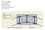
This diagram from that document shows exactly what I was asking and also seems to confirm what I thought, that there is axial/lateral play required.

Screenshot 2022-11-24 at 13.48.16.png

Still interested to learn how power is transferred to these middle axles when they are displaced. Particularly in past times with steam locos.
 

12LDA28C

Established Member
Joined
14 Oct 2022
Messages
3,361
Location
The back of beyond
Thanks!

This diagram from that document shows exactly what I was asking and also seems to confirm what I thought, that there is axial/lateral play required.

View attachment 124232

Still interested to learn how power is transferred to these middle axles when they are displaced. Particularly in past times with steam locos.
Locos have been built with Co-Co wheel arrangements for many years, it's certainly not new to the Class 99s.

Given that traction motors are axle-hung, I assume they either move with the axle, or allow movement of the axle within the motor. I'm sure plenty of people here will know more.
 

ijmad

Established Member
Joined
7 Jan 2016
Messages
1,812
Location
UK
Apparently another option is to just have unflanged middle wheels, so they can slide around on the railhead. Potentially an unflanged wheel could lose contact altogether on tight radius curves, but that's unlikely to be a location where you need to get all the power down anyway.
 

edwin_m

Veteran Member
Joined
21 Apr 2013
Messages
25,013
Location
Nottingham
Apparently another option is to just have unflanged middle wheels, so they can slide around on the railhead. Potentially an unflanged wheel could lose contact altogether on tight radius curves, but that's unlikely to be a location where you need to get all the power down anyway.
You wouldn't want the unflanged wheel to go off the side of the rail, otherwise the suspension would push it down and risk a derailment. I don't believe any recent locomotive or rolling stock has or them, but 2-10-0 steam locomotives did, and they are now banned from Network Rail due to incompatible pointwork being introduced some time after they disappeared from the main line. The curves on heavy rail are sufficiently gentle that the offset of a centre wheel is small enough to be taken up by a small amount of lateral play or steerable axles.
 

snowball

Established Member
Joined
4 Mar 2013
Messages
7,784
Location
Leeds
Apparently another option is to just have unflanged middle wheels, so they can slide around on the railhead. Potentially an unflanged wheel could lose contact altogether on tight radius curves, but that's unlikely to be a location where you need to get all the power down anyway.
Many decades ago I had a Hornby Dublo train set which I think adopted that solution.
 

ijmad

Established Member
Joined
7 Jan 2016
Messages
1,812
Location
UK
You wouldn't want the unflanged wheel to go off the side of the rail, otherwise the suspension would push it down and risk a derailment. I don't believe any recent locomotive or rolling stock has or them, but 2-10-0 steam locomotives did, and they are now banned from Network Rail due to incompatible pointwork being introduced some time after they disappeared from the main line. The curves on heavy rail are sufficiently gentle that the offset of a centre wheel is small enough to be taken up by a small amount of lateral play or steerable axles.

That makes sense as I was reading about how steam locomotives dealt with curves when this solution was mentioned. Thanks for the extra info!
 

hwl

Established Member
Joined
5 Feb 2012
Messages
7,423
EMD have had the option of steerable outer axles on their 3 axle bogies since the mid 1970s which reduces rolling / starting resistance on curves and also improves tractive effort.

In reality unlike the SKF diagram above the angle of attack on the leading axle on curves is the main issue on 3 axle bogies (the angle of attack on the mid and trailing axles is much lower and less problematic).
 

XAM2175

Established Member
Joined
8 Jun 2016
Messages
3,469
Location
Glasgow
Is the simple answer that the middle axle is somewhat free to move laterally? Is this also the case on steam locomotives that often seem to have various sizes of wheels all the way down?
EMD have had the option of steerable outer axles on their 3 axle bogies since the mid 1970s which reduces rolling / starting resistance on curves and also improves tractive effort.
EMD's name for it is radial steering. It's reasonably common in the US and (IIRC) used here on Class 66s, and you might find a bit more info under that term.

This research paper has a few freely-viewable diagrams that illustrate the principle:
 

ac6000cw

Established Member
Joined
10 May 2014
Messages
3,181
Location
Cambridge, UK
EMD's name for it is radial steering. It's reasonably common in the US and (IIRC) used here on Class 66s, and you might find a bit more info under that term.

There's an interesting thread on the US Trains magazine forum on the development of the EMD radial-steering bogie ('truck' in the US) - https://cs.trains.com/trn/f/741/t/281717.aspx

Also an old EMD design paper about reducing weight transfer between axles in their HT-C bogie (50 years ago) - https://utahrails.net/loconotes/EMD_HTC-Truck_ASME_72-RT-3_March-1972.pdf
 
Status
Not open for further replies.

Top