GRALISTAIR
Established Member
I have heard it put differently- Britains problem is, it won the second word war!We also didn't have to rebuild the whole thing from scratch after 1945.
I have heard it put differently- Britains problem is, it won the second word war!We also didn't have to rebuild the whole thing from scratch after 1945.
It's true in so many ways, not just infrastructure!I have heard it put differently- Britains problem is, it won the second word war!
The picture of the “comfortable space” 9 seat waiting room must be the most uninviting image I’ve ever seen of such a facility. NR media had better not branch out into estate agency.
NR press release

Now open: Market Harborough’s upgraded facilities
Better facilities are now available for passengers at Market Harborough station, as Network Rail unveils the brand-new toilet block and waiting room today (Friday 22 July).www.networkrailmediacentre.co.uk
From #5531
The new nine-seat waiting room now provides passengers with a comfortable space to wait for their train and enjoy a drink from the water fountain. A five-cubicle toilet block is also now available for rail users, complete with an accessible toilet and baby changing facilities.
Are the folks of Market Harborough particularly incontinent? Is there an over provision of toilets or an under provision of waiting room seats?
I‘m really surprised NR’s usual exaggerated style of PR didn’t announce that as 14 seats…
Five toilet cubicles.... Two male, two female and one disabled???
In the "nine seat waiting room" six of the seats are marked as "keep free for social distancing". So there's only three. It does look like a detention centre.Nine seat waiting room?
About enough for a large MPV, not a train.


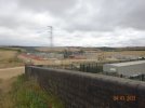
Presumably they need strengthening as they need to support the weight of the cables running down to the substation below and probably need to ensure the position of the main conductors are held more rigid in high wind speeds.Thanks for the updated view of the grid compound @Flying Phil - did you notice there have been significant alterations to the three western arms of the pylon? Are the pylon arms lengthened? It’s hard to tell, but they can be compared with the original view in post #5393. It looks as though the highest arm is longest, I think a view along the line of the route would probably show it more accurately. I suppose they’ll do something similar on the other side in due course.
Yes, and lengthening to keep those droppers clear of each other. Would be very interesting to see how they actually do the work, especially how they change the main cable carrying insulators over to that delta arrangement.Presumably they need strengthening as they need to support the weight of the cables running down to the substation below and probably need to ensure the position of the main conductors are held more rigid in high wind speeds.
You'd be surprised how much they can do live these days although i doubt this was done that way must have been an outage on that side of the pylon and they will get a corresponding one the other side. These outages are hard to come by over Autumn / Winter due NG need far more transmission capacity especially on the Midlands to London/SE circuitsYes, and lengthening to keep those droppers clear of each other. Would be very interesting to see how they actually do the work, especially how they change the main cable carrying insulators over to that delta arrangement.
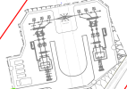
It seems that they are planning to run the droppers at a angle to the vertical, but keep them all in the same plane as the pylon arms. So the new delta arrangement of insulators on the pylon will be to keep the main cables in the same position even under extra sideways force from the droppers. At least, that what I infer from the layout that we saw in the Flood Risk Assessment: https://www.kettering.gov.uk/planx_downloads/5.FloodRiskAssessment.0791.2017.KET.031017.pdfPresumably they need strengthening as they need to support the weight of the cables running down to the substation below and probably need to ensure the position of the main conductors are held more rigid in high wind speeds.


Probably should be one male, two female, one disabled and one non-binary these days...Five toilet cubicles.... Two male, two female and one disabled???
What do those capacity statistics mean in terms of the question posed below?The normal Grid transformer for an ATFS is 2 x 40 MVA, though this can be stretched to 88MVA. The largest pre-AT feeders have a 2 x 26.5MVA transformer. The precise rating depends on whether it is naturally cooled or force cooled. The transformers actually belong to the Grid. They can be very expensive - one single installation for HS2 coming in at £92.5M!
WAO
Could it also cope with electric operations between Leicester and Nottingham for Leicester to Grimsby services and Nottingham to Derby for the various regional service groups?I've been thinking about my local MML Grid Supply Point at Ratcliffe-on-Soar. I understand from previous posts that the grid connection (due to be located just next to the railway south of the A453 bridge) has been ordered from National Grid.
I know these are very expensive items with long lead times.
Does anyone know what capacity has been specified? e.g. Has it been sized to supply 4x810 per hour on the MML? Does it include the 4/5tph between Nottingham and Derby (currently diesel but could be bi-mode in future)? Did the calculations include the prospect of electric freight routes? And the prospect of electo-diesels like the Class 93 and 99, so that all freight could in principle be electric traction? And will it also have capacity to also supply HS2 trains which will be passing through or close by here?*
* According to the IRP, which of course should be treated as gospel.
Plenty of capacity to do everything needed including regional DMU replacement and freight plus some resilience.What do those capacity statistics mean in terms of the question posed below?
Could it also cope with electric operations between Leicester and Nottingham for Leicester to Grimsby services and Nottingham to Derby for the various regional service groups?

Today (Monday 25 July), essential work to upgrade a bridge in Oakley, Bedfordshire has begun, keeping it strong and reliable for drivers and passengers over future decades.
Highfield Road bridge, which carries road traffic over the Midland Main Line between Bedford and Wellingborough, will be reinforced over the coming months with new support for the historic foundations.
This will make sure that the bridge remains stable, secure and safe for both road and rail traffic well into the future. Teams will also use this time to inspect and repair any structural damage to reduce the need for future maintenance.
To do this safely, temporary scaffolding will be erected, and this section of Highfield Road will be partially closed to cars on weekdays from Monday 25 July until Friday 2 September*. The road will remain fully open in both directions during weekends and pedestrians will always be able to cross.
Gary Walsh, Route Director for East Midlands at Network Rail said: “Safety is our top priority and completing this essential upgrade in Oakley will mean that Highfield Road bridge remains safe and reliable for both drivers and rail passengers for many years to come.
“We’ve worked carefully with the local authorities to identify the least disruptive time to carry out the work, and we have chosen to do it during the school summer holidays to keep the impact on the community to a minimum. I do apologise in advance to those who are affected by this work.”
Some early morning and late night services will be retimed to keep workers safe, so passengers should check before they travel with National Rail Enquiries.
Notes to Editors
*Highfield Road will be closed from Monday 25 July until Friday 2 September on weekdays only. Each week the road will be partially closed from 08:00 Monday until 17:00 Friday.
I just checked on an MML cab ride video, and this is quite a high brick arch bridge, (four arches), it would have been completely clear of the electrification equipment, so I suspect this is a completely unrelated task.A Network Rail press release on works to an overbridge about 3 miles north of Bedford. Surprising this wasn't done as part of the Beford-Kettering electrification.

Work to bolster a Bedfordshire bridge gets underway
Today (Monday 25 July), essential work to upgrade a bridge in Oakley, Bedfordshire has begun, keeping it strong and reliable for drivers and passengers over future decades.www.networkrailmediacentre.co.uk
The embankment north of said bridge is also listed as "poor earth works", and Oakley Viaduct (Slow Lines) is also falling into disrepair. Both those contribute to the 20mph PSR on the Up Slow in the area; although the two problems aren't directly related, the bridge work and the poor condition of the viaduct are probably related to the poor earthworks.I just checked on an MML cab ride video, and this is quite a high brick arch bridge, (four arches), it would have been completely clear of the electrification equipment, so I suspect this is a completely unrelated task.
Keeping it on topic, I went back and had a quick look at the business case (link below), and as expected it doesn't try to unpick the journey time benefits, which are all measured against a 2016 baseline of fleet and timetable. Most the generalised journey time benefits generally come from the timetable rewrite (doubled Corby services & deletion of InterCity calls south of Kettering)
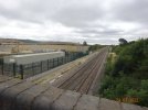
In minor news, a new foundation has appeared next the footbridge on Braybrooke Road in Market Harborough, I do wonder about the scheduling of projects like this because, from the outside, this type of thing does make it all look a bit random (but I'm sure the contractors know what they're doing).


Though on a purely practical level, every bombed overbridge that needed to be rebuilt was an immediate opportunity to build in electrification clearances (applies to countries like the Netherlands as well). Are we also suffering (so far) from having chosen 25kV over (say) 15kV - which presumably requires lower clearances?Yes - although the problem is largely psychological. The whole "Germany was bombed to smithereens which enabled them to start with a fresh slate" argument seems philosophically unsound to me.
25kV the sensible choice as more efficient. Will suffer much less heating losses than 15kV.Though on a purely practical level, every bombed overbridge that needed to be rebuilt was an immediate opportunity to build in electrification clearances (applies to countries like the Netherlands as well). Are we also suffering (so far) from having chosen 25kV over (say) 15kV - which presumably requires lower clearances?
So a gravity pad or a traditional augered hole and filled with concrete?
I realise that 25kV is massively superior once installed (hence the “so far”). The thought was more whether its need for greater clearances has “helped” to push costs into the range that has kept frightening the penny-pinchers. The perfect being the enemy of the good, as it were. Whatever the answer, we are where we are….25kV the sensible choice as more efficient. Will suffer much less heating losses than 15kV.
Silly me. Just had a fresh look at the photo. Of course you are correct.rather small for a gravity pad!
That looks to me to be an "auger and cast" foundation, perhaps due to poor ground or harder ground. I'd estimate it's the latter as it's right next to where the course of the old road was before the crossing became a footpath and then abolished completely in favour of the current footbridge.rather small for a gravity pad!
After reexamination I agree.That looks to me to be an "auger and cast" foundation, perhaps due to poor ground or harder ground.
There's a few similar ones still curing north of Market Harborough.
The clearance required for 15kV vs 25kV isn't a linear thing. Most of the clearance for catenary supported conductors is down to the physical movement, creepage and mechanical movement from pantograph dynamics. In dry air, the distance that a supply could jump is about 1mm/kV. Even in the contaminated environment that OLE has to work in, a gap of say 50mm would be adequate. Now add to the the upthrust of the pantograph, the vibration and standing waves, - particularly where registration is in close areas, then there is allowance for thermal expansion/contraction, and you can see that special clearances of around 200mm are predominately there to protect infrastructure where pantograph bounce can make medium toleranced OLE encroach grounded infrastructure.I realise that 25kV is massively superior once installed (hence the “so far”). The thought was more whether its need for greater clearances has “helped” to push costs into the range that has kept frightening the penny-pinchers. The perfect being the enemy of the good, as it were. Whatever the answer, we are where we are….
In the current standards the real killer is that the default gap is sized not to transmit lightning to structures (+ allowance for upward movement etc.) rather than just the rail supply voltage.The clearance required for 15kV vs 25kV isn't a linear thing. Most of the clearance for catenary supported conductors is down to the physical movement, creepage and mechanical movement from pantograph dynamics. In dry air, the distance that a supply could jump is about 1mm/kV. Even in the contaminated environment that OLE has to work in, a gap of say 50mm would be adequate. Now add to the the upthrust of the pantograph, the vibration and standing waves, - particularly where registration is in close areas, then there is allowance for thermal expansion/contraction, and you can see that special clearnces of around 200mm are predominately there to protect infrastructure where pantograph bounce can make medium toleranced
