• Our new ticketing site is now live! Using either this or the original site (both powered by TrainSplit) helps support the running of the forum with every ticket purchase! Find out more and ask any questions/give us feedback in this thread!

MML Electrification: progress updates

PJM

Member
Joined
20 Aug 2021
Messages
203
Location
Market Harborough
In addition to my previous post, several STC masts appear to have sprung up overnight from Great Bowden, along the straight towards East Langton. Approx 13. Some more TTC uprights on the Harborough side of the A6 bridge too, towards the commencement of the 85mph speed restriction.
Absolutely, a quick drive through Great Bowden today confirms this.
 
Sponsor Post - registered members do not see these adverts; click here to register, or click here to log in
R

RailUK Forums

59CosG95

Established Member
Joined
18 Aug 2013
Messages
6,710
Location
Between Beeston (Notts) & Bedlington
Updates on the MMLE Map:
Piling between East Langton & Newton Harcourt (22:00 - 06:00) - Fri 03/02/23 to Sat 18/02/23 & Fri 24/02/23 to Fri 03/03/23
Piling between Braybrooke & Great Bowden (22:00 Sat 18/02/23 to 06:00 Sun 19/02/23? - unclear)
Mast & Wire installation between Rushton & Braybrooke (23:30 Sat 25/02/23 to 07:30 Fri 03/03/23); this goes through the Desborough Gap
Vegetation Management between Great Bowden & South Wigston (07:00 Sat 04/02/23 to 17:00 Sun 12/03/23)
DEP Installation within Market Harborough Station (22:00 Sat 04/02/23 to 08:00 Fri 03/03/23)
 

PJM

Member
Joined
20 Aug 2021
Messages
203
Location
Market Harborough
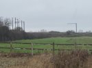
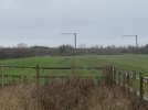
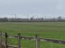
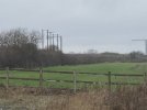
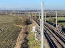
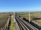
Shots taken from Langton Road, once again near the A6. Cantilevers have appeared! Driving south on the A6 I counted approximately 10 cantilevers and about 20 assorted masts ( very rough figures) . I will try and get better shots from the footbridge in the next few days.

IMG_2402.JPGIMG_2407.JPGIMG_2408.JPGIMG_2409.JPG
 

WAO

Member
Joined
10 Mar 2019
Messages
888
The third picture (IMG_2408) above shows (IMHO) just how neat and unobtrusive modern functional trussed OLE can be.

If the GWML had had this it would have won a Civic Trust environmental award.

Good Engineering.

WAO
 

zwk500

Veteran Member
Joined
20 Jan 2020
Messages
14,978
Location
Bristol
The third picture (IMG_2408) above shows (IMHO) just how neat and unobtrusive modern functional trussed OLE can be.

If the GWML had had this it would have won a Civic Trust environmental award.

Good Engineering.

WAO
I respectfully, disagree. TTC's need to be heavier to support the wider lever action, and the truss formation is far more intrusive than contemporary lines in Europe, e.g. the Betuweroute. I completely understand the economic rationale for single pilings, but lets not get away from the fact that STCs would be lighter on the eye.
 

WAO

Member
Joined
10 Mar 2019
Messages
888
You are quite right that it could be better - it's just a relief not to have the shipyard cranes that we have down here on the GWR!

WAO
 

AM9

Veteran Member
Joined
13 May 2014
Messages
15,218
Location
St Albans
Still far more visually intrusive than previous models...
View attachment 127022
I just get a green rectangle fpr the upper picture you've included, but the lower pictire of a STC looks like the 'low uplift' type of installation as is used on MML south. The reduced uplift performance caused by the smaller distance between the catenary and the contact wire has been suggested as the reason for upgrading the MML (S) as part of the preparations for the introduction of 125mph electric train operation. This is particularly so in the stretch from Hendon to Mill Hill which runs alongside the M1.
 

GRALISTAIR

Established Member
Joined
11 Apr 2012
Messages
9,332
Location
Dalton GA USA & Preston Lancs
I respectfully, disagree. TTC's need to be heavier to support the wider lever action, and the truss formation is far more intrusive than contemporary lines in Europe, e.g. the Betuweroute. I completely understand the economic rationale for single pilings, but lets not get away from the fact that STCs would be lighter on the eye.
Agreed. The bending moment on a TTC is greater too.

You are quite right that it could be better - it's just a relief not to have the shipyard cranes that we have down here on the GWR!

WAO
Also agreed.
 

59CosG95

Established Member
Joined
18 Aug 2013
Messages
6,710
Location
Between Beeston (Notts) & Bedlington
I just get a green rectangle fpr the upper picture you've included, but the lower pictire of a STC looks like the 'low uplift' type of installation as is used on MML south. The reduced uplift performance caused by the smaller distance between the catenary and the contact wire has been suggested as the reason for upgrading the MML (S) as part of the preparations for the introduction of 125mph electric train operation. This is particularly so in the stretch from Hendon to Mill Hill which runs alongside the M1.
The STC in the picture is actually one of the "high uplift" ones seen on the ECML. I think NWR are having a serious look at this, but the scope still needs to be signed off.
 

zwk500

Veteran Member
Joined
20 Jan 2020
Messages
14,978
Location
Bristol
Photos of the various equipment are found in this document: https://assets.publishing.service.g...ead-line-equipment-ole-support-structures.pdf. Part 2 of the report is the important bit for the images.
[link to UK Government report into use of OLE masts for radio antennae mounting, images included within]

I think what makes the GWML particularly egregious is the amount of steel protruding above the horizontal beams. Although it is also generally weightier, I don't think it's much worse in that regard than the 60s stuff out of Euston.
 

LNW-GW Joint

Veteran Member
Joined
22 Feb 2011
Messages
21,010
Location
Mold, Clwyd
I think what makes the GWML particularly egregious is the amount of steel protruding above the horizontal beams. Although it is also generally weightier, I don't think it's much worse in that regard than the 60s stuff out of Euston.
Is it me, or was the original WCML wiring all "below the beams" (mostly 4-track portals)?
I'm sure extra cantilevers appeared above the portals during WCRM, perhaps to cope with the heavier/higher-tensioned catenary for 125/140mph.
My perception is that the WCML OHLE is more complicated than it used to be.
 

zwk500

Veteran Member
Joined
20 Jan 2020
Messages
14,978
Location
Bristol
Is it me, or was the original WCML wiring all "below the beams" (mostly 4-track portals)?
I'm sure extra cantilevers appeared above the portals during WCRM, perhaps to cope with the heavier/higher-tensioned catenary for 125/140mph.
My perception is that the WCML OHLE is more complicated than it used to be.
There's definitely new stuff in between the old portals where stations were rebuilt or speeds increased. I only started using the WCML in 2017 so haven't got a clue what it was like before WCRM.

Having said that, here in NL much of the catenary wire is suspended above the portal frame without it looking massively untidy. Of course here it's DC so simpler wiring, and 1.5KV so less clearance required, and speeds are generally lower so the forces involved in tensioning the wire are less.
See: https://www.greencarreports.com/new...s-now-running-on-100-percent-renewable-energy for a photo of some fairly typical Dutch structures.
 

Attachments

  • 1673773562523.png
    1673773562523.png
    3.5 MB · Views: 65

edwin_m

Veteran Member
Joined
21 Apr 2013
Messages
26,609
Location
Nottingham
Having said that, here in NL much of the catenary wire is suspended above the portal frame without it looking massively untidy. Of course here it's DC so simpler wiring, and 1.5KV so less clearance required, and speeds are generally lower so the forces involved in tensioning the wire are less.
See: https://www.greencarreports.com/new...s-now-running-on-100-percent-renewable-energy for a photo of some fairly typical Dutch structures.
Other things being equal, DC wiring is usually heavier than AC, as it has to carry higher currents.
 

AM9

Veteran Member
Joined
13 May 2014
Messages
15,218
Location
St Albans
There's definitely new stuff in between the old portals where stations were rebuilt or speeds increased. I only started using the WCML in 2017 so haven't got a clue what it was like before WCRM.

Having said that, here in NL much of the catenary wire is suspended above the portal frame without it looking massively untidy. Of course here it's DC so simpler wiring, and 1.5KV so less clearance required, and speeds are generally lower so the forces involved in tensioning the wire are less.
See: https://www.greencarreports.com/new...s-now-running-on-100-percent-renewable-energy for a photo of some fairly typical Dutch structures.
That portal arrangement is typical of 1500V OLE, if the GE and Manchester Glossop lines were still DC, their catenary wires would still be strung over the frames.
 

59CosG95

Established Member
Joined
18 Aug 2013
Messages
6,710
Location
Between Beeston (Notts) & Bedlington
I think what makes the GWML particularly egregious is the amount of steel protruding above the horizontal beams. Although it is also generally weightier, I don't think it's much worse in that regard than the 60s stuff out of Euston.
The main reason why the masts protruded so often above the booms on portals & TTCs (particularly with the "hook & pin" TTCs, but also the Monoboom Anchors) was for ATF supporting purposes. Vertical "gallows" ATF supports had the highest protrusion:
1673788665424.png
Rather strangely, this method of ATF support was chosen to reduce wind loading on the masts!
Much of the GWML had to be larger to take the wider spacing between tracks (a legacy of Brunel's Broad Gauge) into account as well, so that's why some of the masts are fairly beefy there.
 

zwk500

Veteran Member
Joined
20 Jan 2020
Messages
14,978
Location
Bristol
The main reason why the masts protruded so often above the booms on portals & TTCs (particularly with the "hook & pin" TTCs, but also the Monoboom Anchors) was for ATF supporting purposes. Vertical "gallows" ATF supports had the highest protrusion:
Rather strangely, this method of ATF support was chosen to reduce wind loading on the masts!
Much of the GWML had to be larger to take the wider spacing between tracks (a legacy of Brunel's Broad Gauge) into account as well, so that's why some of the masts are fairly beefy there.
Thanks for the explanations.
 

Bald Rick

Veteran Member
Joined
28 Sep 2010
Messages
31,999
Is it me, or was the original WCML wiring all "below the beams" (mostly 4-track portals)?
I'm sure extra cantilevers appeared above the portals during WCRM, perhaps to cope with the heavier/higher-tensioned catenary for 125/140mph.

No, the catenary wire was often (but not always) above the booms Pre re wiring in the early 2000s.

The method of support did change though, hence the new cantilevers.
 

Nottingham59

Established Member
Joined
10 Dec 2019
Messages
2,594
Location
Nottingham
Much of the GWML had to be larger to take the wider spacing between tracks (a legacy of Brunel's Broad Gauge) into account as well, so that's why some of the masts are fairly beefy there.
I understand the masts also had to be set significantly further away from the tracks than had been planned, because the piles kept cutting into buried signalling and communications cables which weren't where people expected them to be.
 

WesternBiker

Member
Joined
26 Aug 2020
Messages
675
Location
Farnborough
The main reason why the masts protruded so often above the booms on portals & TTCs (particularly with the "hook & pin" TTCs, but also the Monoboom Anchors) was for ATF supporting purposes. Vertical "gallows" ATF supports had the highest protrusion:
View attachment 127043
Rather strangely, this method of ATF support was chosen to reduce wind loading on the masts!
Much of the GWML had to be larger to take the wider spacing between tracks (a legacy of Brunel's Broad Gauge) into account as well, so that's why some of the masts are fairly beefy there.
Is it not also the case that the GWML structures are designed to facilitate the higher tensioning to permit 140mph running?
 

PJM

Member
Joined
20 Aug 2021
Messages
203
Location
Market Harborough
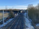
A couple of shots looking north from the footbridge just north of the A6 road bridge.

IMG_2424.JPGIMG_2425.JPG

Looking south towards the A6 bridge. There are two or three masts south of that bridge-a bit tricky to see.
IMG_2426.JPG
 

TheHSRailFan

Member
Joined
16 Jun 2018
Messages
285
Honestly great to see the speed at which the Market Harborough to Wigston section of the electrification is gone. It does mainly seem like it is of the sections where the lineside is mainly flat with no real obstacles which are been done quickly and efficiently.
 

59CosG95

Established Member
Joined
18 Aug 2013
Messages
6,710
Location
Between Beeston (Notts) & Bedlington
Lovely shots @PJM! The access to the footpath at bridge SPC3-28 should still be reachable off Langton Rd shortly before it crosses the A6, unless contractors have fenced it off now.
I also have it on good authority that, south of Bedford, all Booster Transformers have been removed (as far as Kentish Town SATS anyway).

Those bigger masts in the 1st & second picture look to me to be for a Mid-Point Anchor portal, judging by the extra trial holes south of the masts, and the height of the masts makes me think they'll anchor the ATF as well as the catenaries on the DM/UM. Perfect sense for the ATF to go into a trough there, as it has to pass under 3 overbridges and an overhead power line in fairly rapid succession.
 

PJM

Member
Joined
20 Aug 2021
Messages
203
Location
Market Harborough
On checking Google maps 59CosG95, you are absolutely correct about the footpath to bridge SPC3-28, I didn`t realise there was another bridge there! Will check it out next time.
 

SouthEastBuses

On Moderation
Joined
15 Nov 2019
Messages
1,800
Location
uk
A couple of shots looking north from the footbridge just north of the A6 road bridge.

View attachment 127182View attachment 127183

Looking south towards the A6 bridge. There are two or three masts south of that bridge-a bit tricky to see.
View attachment 127184

Is this between Market Harborough and Leicester? If that's the case, then it's good to see MML electrification progressing further than we originally thought it would have!

Also, on a more general note, let me guess, the Midland Mainline is also using the 2x25 kV system? (as found on the GWML, HS1, and high speed railway lines in France and Italy)
 

Nottingham59

Established Member
Joined
10 Dec 2019
Messages
2,594
Location
Nottingham
the Midland Mainline is also using the 2x25 kV system?
By 2x25kV, do you mean using ATF (autotransformer feed) which supplies power to the line through two cables at +25kV and -25kV? With intermediate transformers to transfer power from the separate ATF cable (at -25kV) onto the catenary wires (at +25kV)?

If so, then I understand only parts of the MML use this, but the rest is "ATF-ready" if needed to boost the power at a future date. This post (above) has more details:
Currently, only the section between Kentish Town SATS (Sectioning Autotransformer Site) & Borehamwood ATFS (Autotransformer Feeder Station) is equipped with ATF. This was done as part of the Thameslink Programme works.

The new TSCs at Napsbury (KO1a), Ampthill (KO1), Bedford (KO1), Irchester (KO1), Harrowden (KO1) and Kettering North (KO1), along with the MPTSCs at East Hyde (KO1a) and Sharnbrook (KO1) are all autotransformer ready. Long Meadow Farm (Chalton) ATFS (also KO1), which came online last Christmas, also has AT capability, and Braybrooke ATFS (KO1a) will have it from the outset.
[EDIT. By -25kV, I mean 25kV AC which is 180 degree out of phase with the catenary supply]
 

59CosG95

Established Member
Joined
18 Aug 2013
Messages
6,710
Location
Between Beeston (Notts) & Bedlington
Fantastic! I wonder when will works start on the next section (north of Wigston)?
Shortly after the contractors are announced, I'll wager.
Currently, RS1 (Mkt H'boro' to South Wigston) has been tacked on to KO1a of the original chopped programme (Kettering - Mkt H'boro') as it's a relatively easy win (two tracks, no additional grid connections, signalling already compliant etc.)

RS2 through RS8 are still out for competitive tender.
 

Top